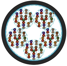
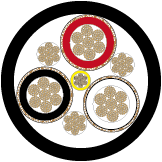
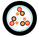
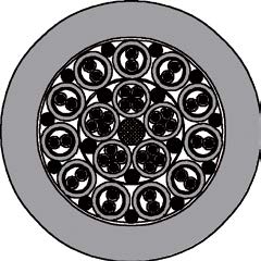
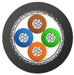
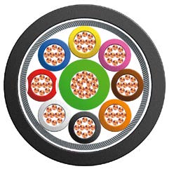
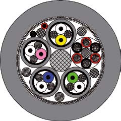
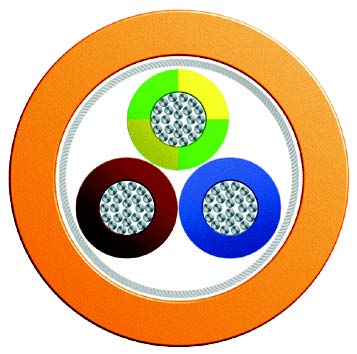
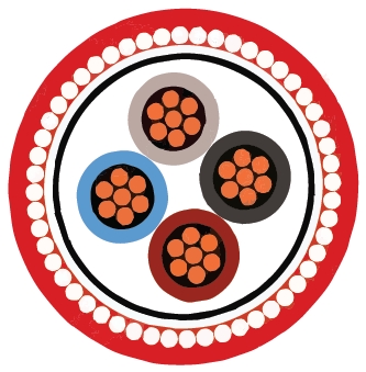
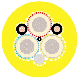
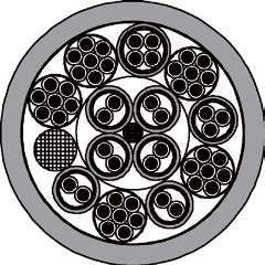
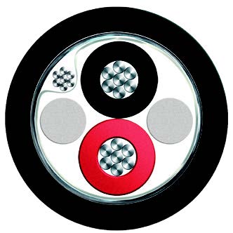
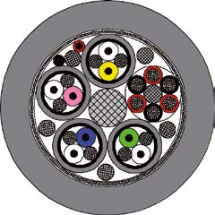
K23 carries remote-control and teletransmission circuits on metro and suburban railway infrastructure. The construction combines PE-insulated copper conductors, a laminated aluminium moisture barrier, an LSZH inner sheath, double steel tape armour and an LSZH outer sheath. Quad or pair assembly follows the specified cable arrangement. The range is organised by conductor diameter and pair count, with electrical ratings changing between conductor sizes.
NF F 55-623
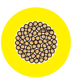
Conductors : Copper wire, 0.6, 0.8, 1.0 or 1.2 mm nominal diameter.
Insulation : Solid polyethylene.
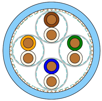
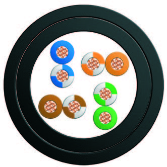
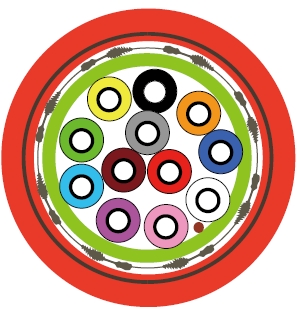
Cabling Element : Four conductors are twisted to form a star quad. For 1 & 4 pair cables, conductors shall be twisted in pairs.
Stranding : Quads are stranded in helically laid concentric layers or units to form the cable core.
Core Wrapping : Plastic tape(s) with overlapping.
Moisture Barrier : One laminated sheath made of aluminium tape coated with PE-Copolymer on at least one side is applied with longitudinally overlap.
Inner Sheath : LSZH fi re retardant compound.
Armour : Two helically applied steel tapes.
Outer Sheath : LSZH fire retardant compound.
| Nominal Conductor Diameter | mm | 0.6 | 0.8 | 1.0 | 1.2 |
| Maximum Average DC Conductor Resistance | Ω/km | 64.0 | 36.0 | 23.0 | 16.0 |
| Minimum Insulation Resistance @500 V DC (3min) | MΩ.km | 5000 | 5000 | 5000 | 5000 |
| Maximum Mutual Capacitance @1000Hz (AC) | nF/km | 57.5 | 57.5 | 57.5 | 57.5 |
| Maximum Capacitance Unbalance @800Hz | |||||
| K1 (side to side) | pF/500m | 435 | 435 | 435 | 435 |
| K9-12 (quad to quad) | pF/500m | 220 | 220 | 220 | 220 |
| Operating Voltages | V | 200 | 400 | 500 | 750 |
| Maximum Permissible Current | A | 0.35 | 0.63 | 1.0 | 1.4 |
| Dielectric Strength (DC voltage 1min) | |||||
| Conductor to Conductor | V | 1500 | 2000 | 3000 | 3000 |
| Conductor to Screen | V | 1500 | 1500 | 1500 | 1500 |
Minimum Bending Radius : 8×OD (static) ; 16×OD (dynamic)
Temperature Range : -40℃ to +60℃ (during operation) ; -20℃ to +50℃ (during installation)
| Cable Code | Number of Pairs | Spare pairs | Minimum Sheath Thickness | Maximum Overall Diameter | Nominal Weight | |
|---|---|---|---|---|---|---|
| Inner | Outer | |||||
| mm | mm | mm | kg/km | |||
| 0.6mm Conductor, 0.96mm Insulated Wire (6/10) | ||||||
| BRAIL K23-2Y(L)HBH-2P0.6 | 2 | - | 1.0 | 1.0 | 10.5 | 130 |
| BRAIL K23-2Y(L)HBH-4P0.6 | 4 | - | 1.0 | 1.0 | 14.0 | 171 |
| BRAIL K23-2Y(L)HBH-8P0.6 | 8 | - | 1.0 | 1.0 | 16.5 | 215 |
| BRAIL K23-2Y(L)HBH-14P0.6 | 14 | - | 1.0 | 1.2 | 17.5 | 290 |
| BRAIL K23-2Y(L)HBH-20P0.6 | 20 | - | 1.0 | 1.2 | 18.5 | 350 |
| BRAIL K23-2Y(L)HBH-28P0.6 | 28 | - | 1.0 | 1.4 | 21.0 | 441 |
| BRAIL K23-2Y(L)HBH-38P0.6 | 38 | - | 1.0 | 1.4 | 21.5 | 533 |
| BRAIL K23-2Y(L)HBH-56P0.6 | 56 | - | 1.0 | 1.4 | 23.0 | 700 |
| BRAIL K23-2Y(L)HBH-84P0.6 | 84 | - | 1.0 | 1.6 | 28.0 | 970 |
| BRAIL K23-2Y(L)HBH-112P0.6 | 112 | - | 1.0 | 1.6 | 30.5 | 1190 |
| BRAIL K23-2Y(L)HBH-168P0.6 | 168 | 2 | 1.0 | 1.8 | 38.0 | 1847 |
| BRAIL K23-2Y(L)HBH-224P0.6 | 224 | 2 | 1.0 | 2.0 | 44.0 | 2675 |
| BRAIL K23-2Y(L)HBH-280P0.6 | 280 | 2 | 1.0 | 2.0 | 51.0 | 3185 |
| BRAIL K23-2Y(L)HBH-336P0.6 | 336 | 4 | 1.0 | 2.0 | 57.0 | 3680 |
| BRAIL K23-2Y(L)HBH-392P0.6 | 392 | 4 | 1.0 | 2.0 | 58.5 | 4168 |
| BRAIL K23-2Y(L)HBH-448P0.6 | 448 | 4 | 1.0 | 2.2 | 67.0 | 4647 |
| BRAIL K23-2Y(L)HBH-784P0.6 | 784 | 4 | 1.0 | 2.2 | 90.5 | 7406 |
| BRAIL K23-2Y(L)HBH-896P0.6 | 896 | 6 | 1.0 | 2.2 | 102.5 | 8315 |
| 0.8mm Conductor, 1.27 mm Insulated Wire (8/10) | ||||||
| BRAIL K23-2Y(L)HBH-2P0.8 | 2 | - | 1.0 | 1.0 | 11.5 | 155 |
| BRAIL K23-2Y(L)HBH-4P0.8 | 4 | - | 1.0 | 1.0 | 15.5 | 216 |
| BRAIL K23-2Y(L)HBH-8P0.8 | 8 | - | 1.0 | 1.2 | 17.5 | 298 |
| BRAIL K23-2Y(L)HBH-14P0.8 | 14 | - | 1.0 | 1.4 | 20.5 | 412 |
| BRAIL K23-2Y(L)HBH-20P0.8 | 20 | - | 1.0 | 1.4 | 23.0 | 512 |
| BRAIL K23-2Y(L)HBH-28P0.8 | 28 | - | 1.0 | 1.4 | 24.5 | 637 |
| BRAIL K23-2Y(L)HBH-38P0.8 | 38 | - | 1.0 | 1.6 | 26.5 | 805 |
| BRAIL K23-2Y(L)HBH-56P0.8 | 56 | - | 1.0 | 1.6 | 32.0 | 1096 |
| BRAIL K23-2Y(L)HBH-84P0.8 | 84 | - | 1.0 | 1.8 | 39.0 | 1504 |
| BRAIL K23-2Y(L)HBH-112P0.8 | 112 | - | 1.0 | 1.8 | 40.5 | 1880 |
| 1.0mm Conductor, 1.8mm Insulated Wire (10/10) | ||||||
| BRAIL K23-2Y(L)HBH-2P1 | 2 | - | 1.0 | 1.0 | 12.0 | 195 |
| BRAIL K23-2Y(L)HBH-4P1 | 4 | - | 1.0 | 1.2 | 17.5 | 298 |
| BRAIL K23-2Y(L)HBH-8P1 | 8 | - | 1.0 | 1.4 | 20.5 | 431 |
| BRAIL K23-2Y(L)HBH-14P1 | 14 | - | 1.0 | 1.4 | 23.5 | 587 |
| BRAIL K23-2Y(L)HBH-20P1 | 20 | - | 1.0 | 1.6 | 25.0 | 762 |
| BRAIL K23-2Y(L)HBH-28P1 | 28 | - | 1.0 | 1.6 | 29.0 | 981 |
| BRAIL K23-2Y(L)HBH-38P1 | 38 | - | 1.0 | 1.6 | 31.5 | 1243 |
| BRAIL K23-2Y(L)HBH-56P1 | 56 | - | 1.0 | 1.8 | 38.5 | 1683 |
| BRAIL K23-2Y(L)HBH-84P1 | 84 | - | 1.0 | 2.0 | 46.5 | 2340 |
| BRAIL K23-2Y(L)HBH-112P1 | 112 | - | 1.0 | 2.0 | 51.5 | 2944 |
| 1.2mm Conductor, 2.0mm Insulated Wire (12/10) | ||||||
| BRAIL K23-2Y(L)HBH-1P1.2 | 1 | - | 1.0 | 1.2 | 14.0 | 188 |
| BRAIL K23-2Y(L)HBH-2P1.2 | 2 | - | 1.0 | 1.2 | 14.5 | 230 |
| BRAIL K23-2Y(L)HBH-4P1.2 | 4 | - | 1.0 | 1.4 | 20.0 | 357 |
| BRAIL K23-2Y(L)HBH-8P1.2 | 8 | - | 1.0 | 1.4 | 24.0 | 509 |
| BRAIL K23-2Y(L)HBH-14P1.2 | 14 | - | 1.0 | 1.4 | 25.0 | 710 |
| BRAIL K23-2Y(L)HBH-20P1.2 | 20 | - | 1.0 | 1.6 | 29.0 | 950 |
| BRAIL K23-2Y(L)HBH-28P1.2 | 28 | - | 1.0 | 1.6 | 31.5 | 1213 |
Nominal conductor diameters of 0.6, 0.8, 1.0 and 1.2 mm.
A laminated aluminium moisture barrier beneath the armoured sheath construction.
Pair-count schedules include spare pairs where identified for the selected construction.
Specify conductor diameter in millimetres, pair count, spare-pair requirements and route lengths. Check the operating voltage and permissible current in the column for that diameter. The reference to a 1500 V DC railway concerns traction electrification; use the cable’s own electrical ratings for the signalling circuit. Coordinate armour termination, moisture sealing and bend space with the installation design.
K24 LSZH Subway Signalling Cable, Armoured and Unarmoured Options
ZPGU Screened Local Railway Signalling Cable, 1.0 mm² Copper Pairs
ZCO3 & ZCO3-SH Quad Railway Signalling Cable for High-Speed Lines
Are the conductor sizes given in mm²?
The K23 sizes 0.6, 0.8, 1.0 and 1.2 are conductor diameters in millimetres.
What operating voltages are listed?
The table gives 200, 400, 500 and 750 V for 0.6, 0.8, 1.0 and 1.2 mm conductors respectively.
What provides mechanical protection?
Two helically applied steel tapes form the armour between the LSZH sheath layers.
Does the moisture barrier replace sealed terminations?
Cable entries and joints still need sealing appropriate to the route so moisture cannot enter at the ends.
How should pair quantities be specified?
State the required working pairs and any spare pairs, using the exact conductor-diameter section and order code in the schedule.